Views: 222 Author: Amanda Publish Time: 2025-08-12 Origin: Site


Content Menu
>> Why Choose 5-Axis Machining?
● Step-by-Step 5-Axis Machining Process
>> Step 1: CAD Model Import and Design Preparation
>> Step 2: Setup of Work Coordinate System (WCS)
>> Step 3: Defining Stock and Tool Library
>> Step 4: Creating Toolpaths for 5-Axis Machining
>> Step 5: Simulation and Verification
>> Step 6: Machine Setup and Workpiece Fixturing
>> Step 7: Machining Execution
>> Step 8: Post-Machining Inspection and Finishing
● Types of 5-Axis Machines and Their Applications
● Advantages of 5-Axis Machining Over Conventional Methods
● Practical Considerations for Successful 5-Axis Machining
>> 1. What materials can be machined with 5-axis CNC?
>> 2. How does 5-axis machining improve surface finish?
>> 3. Is 5-axis machining more expensive than 3-axis?
>> 4. Can 5-axis machining eliminate the need for multiple setups?
>> 5. What software is typically used for 5-axis programming?
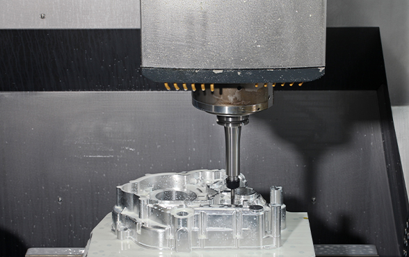
5-Axis machining represents a highly advanced manufacturing process widely used today for creating complex and precise parts that are difficult or impossible to manufacture with conventional 3-axis machines. This technique enables the cutting tool to move in five different axes simultaneously, offering freedom of movement and tooling to reach virtually any surface on a workpiece. This capability is critical in industries such as aerospace, automotive, medical, and mold making, where intricate geometries and high accuracy are demanded.
This comprehensive guide breaks down the 5-axis machining process step-by-step—including setup, operation, programming, and finishing—while explaining the key components and advantages of this technology. The following sections provide detailed insight into how 5-axis machining works, practical considerations, and its applications.

Before diving into the process, it's essential to understand what 5-axis machining entails.
5-Axis machining refers to CNC machining where the cutting tool or the workpiece moves along five different axes simultaneously—three linear (X, Y, Z) and two rotational (usually denoted as A and B or C axes). Unlike traditional 3-axis machines which move only left-right, forward-back, and up-down, 5-axis machines offer additional rotational movement. This allows access to complex shapes with fewer setups and greater precision.
- X-axis, Y-axis, Z-axis: Linear movements in three-dimensional space (left-right, forward-backward, and up-down).
- A-axis: Rotational movement around the X-axis.
- B-axis: Rotational movement around the Y-axis.
- C-axis: Rotational movement around the Z-axis (sometimes used instead of B-axis).
Configurations vary; machines might use two of the rotary axes (A & B, B & C, or A & C) depending on the design.
The primary advantage of 5-axis machining is the ability to approach the workpiece from multiple angles without needing to reposition it manually. This capability significantly improves machining efficiency, precision, and surface finish quality. Complex parts like turbine blades, aerospace components, and precision molds benefit tremendously from this technology.
The process begins with creating a detailed 3D CAD model of the part to be machined. The model must be accurate and free of errors (such as gaps or overlaps), as this ensures the path planning software can generate precise toolpaths.
Supported file formats typically include STEP, IGES, STL, etc. Preparing the model involves reviewing critical features and tolerances that will determine machining strategy. At this stage, designers often consider how to optimize the geometry for machining constraints, such as tool access and material removal rates.
Setting the Work Coordinate System aligns the CAD model to the machine's coordinate space. This step is crucial for precision, as the position and orientation of the part on the machine table impact toolpaths and machining accuracy.
Operators choose the orientation that maximizes tool access and minimizes repositioning during machining. Fixtures are arranged accordingly to hold the workpiece securely while minimizing obstruction to rotating axes.
Next, the raw material stock size and shape are defined in the CAM software. The material block dimensions must match the physical raw material loaded into the machine to avoid collisions or short machining allowances.
A tool library is established, including roughing tools (e.g., face mills, end mills), finishing tools (e.g., ball nose cutters), and special cutters such as tapered or corner radius end mills. Choosing the right tools is essential for efficient chip removal, surface finish, and tool life. Cutting parameters—speeds, feeds, depths of cut—are configured based on material characteristics and tool capabilities.
Toolpaths specifically designed for 5-axis CNC involve simultaneous control of all axes. This adds complexity compared to 3-axis machining, as the orientation of the tool must be calculated dynamically relative to the surface being machined.
Common types of 5-axis toolpaths include:
- Morph toolpaths: Provide smooth surface transitions by continuously varying tool orientation and path direction.
- Multi-axis contouring: Used for complex edges and 3D shapes by contouring the surface through multiple angular orientations.
- Swarf cutting: Allows machining of side walls by keeping the tool blade tangent to the surface, ideal for angled features and thin walls.
A key aspect is tool axis control, which optimizes the tilt and rotation of the tool to maintain ideal cutting angles, avoid collisions with fixtures, and reduce tool deflection. CAM software dedicated to 5-axis machining offers advanced simulation and collision avoidance algorithms, ensuring the tool moves smoothly without unexpected impacts.

After programming, toolpaths undergo firm simulation to verify both the machining strategy and the machine's kinematic limits. Simulation visualizes the tool, workpiece, and fixtures' movements in a virtual space, identifying any potential collisions or inefficiencies.
Dynamic simulation includes checking axis travel limits, verifying smooth transitions in rotational axes, and ensuring no over-travel or unexpected stops during machining. This step prevents expensive errors and reduces machine downtime.
Physically preparing the CNC machine includes:
- Loading and securely fastening the raw material to the machine table or rotary axis.
- Installing and calibrating cutting tools as per the tool library.
- Setting offsets and zero points (work offsets) on the machine for all axes, aligning the machine coordinates with the programmed toolpaths.
Proper fixturing is more critical in 5-axis machining due to complex rotational movements; any looseness or misalignment can cause part deviations or damage.
The machine runs the CNC program, simultaneously moving the cutting tool and rotating axes to shape the part. This multi-axis movement enables:
- Machining of complex surfaces and undercuts without multiple setups.
- Higher precision and superior surface finish.
- Reduced cycle times by performing operations in a continuous flow without manual repositioning.
Machine operators must monitor the process, checking tool wear, coolant flow, and surface quality regularly to ensure consistent production.
After machining, the part undergoes thorough inspection using coordinate measuring machines (CMM) or optical scanners to verify dimensional tolerances and surface finish against design specifications.
Post-processing may include deburring, polishing, heat treatment, or coating to meet functional or aesthetic requirements. This step ensures the part is manufacturing-ready for assembly or shipment.
Various 5-axis machine configurations suit different applications:
- Table/Table Machines: Feature two rotary tables that rotate the workpiece around multiple axes. Ideal for large components requiring complex rotational positioning, such as aerospace parts.
- Head/Head Machines: Both the spindle head and the workpiece have rotational capabilities. Best suited for small, precise parts with intricate details.
- Head/Table Machines: Combine a rotary table and a tilting spindle head, offering high flexibility by allowing versatile rotation combinations. This configuration is common in general machining shops.
Selecting the right machine depends on the workpiece size, complexity, and production volume.
- Flexibility in Part Geometries: 5-axis machines can handle extremely complex shapes, including contoured surfaces, slopes, and undercuts in a single setup.
- Reduced Setup Time: Eliminates the need for multiple repositionings of the workpiece, reducing errors and setup times.
- Improved Accuracy: Simultaneous multi-axis movement minimizes positioning errors caused by re-fixturing.
- Better Surface Finish: Continuous tool orientation adjustment maintains ideal cutting angles, reducing tool marks and vibrations.
- Enhanced Tool Life: Optimized tool paths and angles reduce undue tool stress, extending tool longevity.
- Increased Productivity: Efficient material removal and minimized idle times shorten overall production cycles.
These advantages translate into cost savings and higher product quality, especially critical for high-precision industries such as aerospace, automotive, medical device manufacturing, and advanced mold making.
While the technology offers numerous benefits, manufacturers must address several challenges to maximize results:
- Programming Complexity: 5-axis CNC programs demand highly skilled operators and advanced CAM software to manage tool orientation and collision avoidance.
- Machine Maintenance: The additional rotational axes increase machine complexity and require rigorous maintenance schedules to maintain precision.
- Tool and Fixture Design: Fixtures must securely hold parts without obstructing rotation. Similarly, tools may require specialized designs to match 5-axis dynamics.
- Training and Process Optimization: Staff training and iterative process refinement are essential to harness the full capabilities of 5-axis machining.
By proactively managing these factors, manufacturers can optimize their 5-axis operations, reduce scrap rates, and achieve repeatable results.
5-Axis machining is a powerful technology revolutionizing precision manufacturing by enabling complex part production with high accuracy and efficiency. Its capability to move tools and parts across five axes simultaneously allows manufacturers to reduce setup times, improve surface quality, and produce intricate features that were previously unattainable with traditional machining.
While this process requires advanced programming skills and sophisticated CAM software, the benefits it brings to industries such as aerospace, automotive, and medical manufacturing make it an indispensable process in modern production environments. When combined with rigorous preparation, simulation, and skilled execution, 5-axis machining significantly enhances manufacturing capabilities, quality, and competitiveness.

5-Axis machining supports a wide variety of materials, including metals (aluminum, titanium, steel), plastics, composites, and some ceramics. The choice depends on tooling decisions and machine rigidity.
By continuously adjusting the tool orientation, 5-axis machining maintains optimal cutting angles and constant contact between the tool and workpiece, which reduces tool marks, vibrations, and produces smoother surfaces.
The initial investment and programming complexity are higher for 5-axis machining, but the reduction in setups, increased precision, and faster cycle times often offset these costs in medium to high-volume production.
Yes, it allows machining of complex parts in a single setup by rotating and tilting the tool or workpiece, minimizing repositioning, improving accuracy, and saving time.
Advanced CAM software such as Autodesk PowerMill, Mastercam, Siemens NX, and SolidCAM are widely used for generating 5-axis toolpaths, offering robust simulation and collision detection features.
[1] https://www.mastercam.com/news/blog/what-are-the-axes-in-5-axis-machining/
[2] https://geomiq.com/blog/what-is-5-axis-cnc-machining/
[3] https://mechmansolution.com/blogs/step-by-step-guide-how-to-create-a-5-axis-program-for-cnc-machining/
[4] https://www.lsrpf.com/blog/how-does-5-axis-cnc-machining-work
[5] https://cache.industry.siemens.com/dl/files/454/37335454/att_110322/v1/SIN_WF5_0509_en.pdf
[6] https://www.youtube.com/watch?v=kAVtQhuUq00
[7] https://www.youtube.com/watch?v=ICjcNhjij0A
[8] https://www.heidenhain.com/fileadmin/pdf/en/01_Products/Technische_Dokumentation/TI_Influence_of_Position_Measurement_on_Accuracy_5-Axis_Machining_ID895283_en.pdf
[9] https://www.iqsdirectory.com/articles/cnc-machining/5-axis-cnc-machining.html
[10] https://www.youtube.com/watch?v=gpbECi1EPsg
[11] https://www.youtube.com/playlist?list=PLOmWCgA_Bq9GXQxfjREDO-r6qi7YC-HPx
[12] https://www.okuma.com/guides/5-axis-machining-guide
[13] https://www.youtube.com/watch?v=9FN6_4EM5kU
[14] https://hwacheonasia.com/the-essential-guide-to-5-axis-cnc-machining/
[15] https://www.youtube.com/watch?v=n7Un4cGmiH8
[16] https://www.engineering.com/machinery-basics-what-are-the-axes-in-5-axis/
[17] https://www.youtube.com/watch?v=z4bWL7B-iOg
[18] https://www.pinterest.com/ideas/5-axis-cnc-machine-diagram/905443293121/
[19] https://www.instructables.com/5-Axis-CNC-Milled-Knob-Using-Fusion-360-Manufactur/
[20] https://www.youtube.com/watch?v=bI4JiT_i1cc
content is empty!
How Vacuum Mold Casting Compares to Silicone Mold Casting for Precision Parts
Vacuum Mold Casting vs. Resin Casting: Key Differences You Should Know
Vacuum Mold Casting vs. 3D Printing: Choosing the Best Rapid Prototyping Method
Best Vacuum Mold Casting Services for Precision Manufacturing in 2025
Top Vacuum Mold Casting Manufacturers Delivering High-Quality Prototypes
Best Practices from Leading Vacuum Mold Casting Companies Worldwide
Top Vacuum Mold Casting Providers for Custom Batch Production
How to Choose the Right Vacuum Mold Casting Service for Your Product